

Deltang / RCT-Rx102
Receiver
Receiver
The RCT-Rx102 operates as a normal DSM2 receiver but includes some additional features making it well suited to controlling battery powered locomotives and for operating live steam locomotives (see examples of installations in live steam locos). It is small and lightweight with outputs from seven channels. It can be powered with a supply from 3.2v to 10v DC (though 5v is recommended).
The six servo outputs (Channels 1-6) can be used with an Electronic Speed Controller (ESC) such as the Brian Jones Mac5 or the MTroniks Viper Loco 10, or can be linked to servos to operate the regulator, whistle, blower, gas valve and reverser on a live steam loco. If used with the RCT-Tx22 or RCT-Tx24, or the Deltang Tx22 or Tx24, the output from Channel 1 is used for speed control. The wiring for using an RCT-Rx102 with a third party ESC is very straightforward. If using rechargable batteries, you may want to include a charge socket.
The six servo outputs (Channels 1-6) can be used with an Electronic Speed Controller (ESC) such as the Brian Jones Mac5 or the MTroniks Viper Loco 10, or can be linked to servos to operate the regulator, whistle, blower, gas valve and reverser on a live steam loco. If used with the RCT-Tx22 or RCT-Tx24, or the Deltang Tx22 or Tx24, the output from Channel 1 is used for speed control. The wiring for using an RCT-Rx102 with a third party ESC is very straightforward. If using rechargable batteries, you may want to include a charge socket.
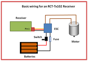
Note: The servo plug connects vertically to the first set of three pins on the receiver, with the white or yellow signal lead uppermost
Features of the RCT-Rx102
Cruise control
If the receiver loses the signal from the transmitter, for example when going through a tunnel, then the outputs hold their settings until the signal is restored. This means that the loco will continue doing what it was instructed to do before the signal was lost. You could switch off the transmitter if, for example, you are running the loco round a continuous circuit and it will continue running.
Binding
Binding the receiver to a transmitter is very straightforward
Selecta
The Selecta switch has twelve positions, enabling the RCT-Tx22/Tx24 to independently control up to twelve locos. By turning the Selecta switch, locos can be brought in and out of service via the transmitter without touching them. On the RCT-Rx102, when the Selecta switch is changed to a different position from the one controlling a particular receiver, the receiver outputs ‘hold’ their settings. It is possible to disable or enable whether an RCT-Rx102 responds to the Selecta switch on RCT and Deltang Tx22 and Tx24 transmitters. To toggle between Selecta-enabled and disabled:
Automatic directional lighting
Signal Pin 6 can power a forward facing LED and signal Pin 7 a backward facing LED on a loco. By default they respond to Channel 1 (the throttle control) or or can be reporgrammed to respond to Channel 3 (Direction switch) if you want the receiver be programmed for 'low off' control.
To toggle whether Directional Lights operate as 'low off' or 'centre off':
Outputs from the signal pins
The default output settings for signal pins (ie the uppermost row) of the RCT-Tx102 are:
The servo output settings for pins 1-3 can be adjusted if, for example, you need to change the direction the servo operates or reduce the length of the servo arm travels (ie the 'throw'). This is useful when using the receiver with live steam locos.
The aerial and range
The aerial must not be shortened or lengthened - it is a precise length to coincide with the wavelength of the signal from the transmitter. The range of the aerial will be affected if it is surrounded by metal. Ideally the aerial should be placed outside the body of the loco and preferably not touching anything metalic. Where this proves difficult to achieve, it is possible to have an extended aerial fitted to the receiver for a small charge.
Here are some examples of places in which the receiver has been fitted in live steam locos.
After installing the receiver, it is important to perform a range test to check that you still have control of your loco to and from all positions on your layout. Range will be adversely affected by the level of charge in the batteries (Rx and Tx) and also buildings (eg sheds), foliage, structures and people which intervene between the transmitter and receiver. Generally, though, you will be following your loco around and so range will probably not be an issue in most gardens. Remember, with cruise control you loco will continue to run at the same speed if the signal is lost.
To change servo output settings for Pins 1 - 3
Only one pin output can be changed at a time.
The middle Neutral position can be changed by up to 32 steps each way.
The LED will flash and throws will change one step per second while a plug is installed.
The LED stays on for 3 seconds when throws are returned to their 'mid' position.
The LED stays on steady when you reach the end of the adjustment range.
High side Throws
Remove all plugs and turn off the receiver and back on again to use all outputs normally.
Cruise control
If the receiver loses the signal from the transmitter, for example when going through a tunnel, then the outputs hold their settings until the signal is restored. This means that the loco will continue doing what it was instructed to do before the signal was lost. You could switch off the transmitter if, for example, you are running the loco round a continuous circuit and it will continue running.
Binding
Binding the receiver to a transmitter is very straightforward
- The large black bind plug (supplied) is connected between signal pin 5 and pin 7 (the signal pins are the uppermost row on the receiver)
- Switch on the receiver. The LED will flash rapidly.
- Remove the bind plug.
- Move the Selecta switch on the RCT-Tx22 (or Tx24) transmitter to the required position.
- Hold down the bind button on the transmitter and turn it on.
- Release the bind button on the transmitter. The LEDs on both the transmitter and the receiver should flash more slowly for several seconds.
- Binding is complete when the LEDs stop flashing and stay on.
Selecta
The Selecta switch has twelve positions, enabling the RCT-Tx22/Tx24 to independently control up to twelve locos. By turning the Selecta switch, locos can be brought in and out of service via the transmitter without touching them. On the RCT-Rx102, when the Selecta switch is changed to a different position from the one controlling a particular receiver, the receiver outputs ‘hold’ their settings. It is possible to disable or enable whether an RCT-Rx102 responds to the Selecta switch on RCT and Deltang Tx22 and Tx24 transmitters. To toggle between Selecta-enabled and disabled:
- Turn off the receiver
- Connect the large black bind plug to Signal pins 4 and 6 (the signal pins are the uppermost ones on the receiver)
- Turn on the receiver
- Remove the plug
Automatic directional lighting
Signal Pin 6 can power a forward facing LED and signal Pin 7 a backward facing LED on a loco. By default they respond to Channel 1 (the throttle control) or or can be reporgrammed to respond to Channel 3 (Direction switch) if you want the receiver be programmed for 'low off' control.
To toggle whether Directional Lights operate as 'low off' or 'centre off':
- Turn off the receiver
- Put the large black bind plug across Signal pins 3 and 5 (the signal pins are the uppermost row on the receiver)
- Turn on the receiver
- Remove the plug
Outputs from the signal pins
The default output settings for signal pins (ie the uppermost row) of the RCT-Tx102 are:
Pin1: Channe 1 Servo [Throttle]
Pin2: Channel 4 Servo
Pin3: Channel 3 Servo [Direction]
Pin4: Channel 2 Servo
Pin5: Channel 5 Servo
Pin6: Auto directional lights (forwards)
Pin7: Auto directional lights (reverse)
Pin8 (side): Channel 6 Servo
The servo output settings for pins 1-3 can be adjusted if, for example, you need to change the direction the servo operates or reduce the length of the servo arm travels (ie the 'throw'). This is useful when using the receiver with live steam locos.
The aerial and range
The aerial must not be shortened or lengthened - it is a precise length to coincide with the wavelength of the signal from the transmitter. The range of the aerial will be affected if it is surrounded by metal. Ideally the aerial should be placed outside the body of the loco and preferably not touching anything metalic. Where this proves difficult to achieve, it is possible to have an extended aerial fitted to the receiver for a small charge.
Here are some examples of places in which the receiver has been fitted in live steam locos.
After installing the receiver, it is important to perform a range test to check that you still have control of your loco to and from all positions on your layout. Range will be adversely affected by the level of charge in the batteries (Rx and Tx) and also buildings (eg sheds), foliage, structures and people which intervene between the transmitter and receiver. Generally, though, you will be following your loco around and so range will probably not be an issue in most gardens. Remember, with cruise control you loco will continue to run at the same speed if the signal is lost.
To change servo output settings for Pins 1 - 3
Only one pin output can be changed at a time.
- Turn off the receiver and then -
- To change Pin 1 (Channel 1 - throttle) put the small (red) bind plug on Signal pins 4 and 5.
- To change Pin 2 (Channel 4) put the small (red) bind plug on Signal pins 5 and 6.
- To change Pin 3 (Channel 3 - direction) put the small (red) bind plug on Signal pins 6 and 7.
- Turn on the receiver. The LED will flash every half second.
- Remove bind plug.
- Turn on the transmitter (and Selecta position) to which the receiver is bound. The LED will flash once every 2 seconds until it locks on to the transmitter signal and then stay off.
- Connect a servo to the chosen output pin
- The servo can now be controlled by the relevant knob or stick on the transmitter
The middle Neutral position can be changed by up to 32 steps each way.
The LED will flash and throws will change one step per second while a plug is installed.
The LED stays on for 3 seconds when throws are returned to their 'mid' position.
The LED stays on steady when you reach the end of the adjustment range.
High side Throws
- To increase high side throws, use the large (black) bind plug to connect the signal pin of Pin 7 to negative.
- To decrease high side throws, use the small (red) bind plug to connect the signal pin of Pin 7 to positive.
- To move the centre position 'up', use the large (black) bind plug to connect the signal pin of Pin 6 to negative.
- To move the centre position 'down', use the small (red) bind plug to connect the signal pin of Pin 6 to positive.
- To increase low side throws, use the large (black) bind plug to connect the signal pin of Pin 5 to negative.
- To decrease low side throws, use the small (red) bind plug to connect the signal pin of Pin 5 to positive.
- To reverse the direction the servo moves, use the large (black) bind plug to connect the signal pin of Pin 4 to negative.
- To return the servo travel to the normal direction, use the small (red) bind plug to connect the signal pin of Pin 4 to positive.
Remove all plugs and turn off the receiver and back on again to use all outputs normally.