Lithium battery protection circuit boards
What are battery protection circuit boards?
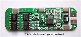
Battery protection circuit boards help to ensure that lithium-ion cells connected in series are protected from over-charging, over-discharging, excess current draw and short circuits.
If li-ion batteries are mishandled, then they will become damaged. At best they will vent gasses but at worst they can burst into flames or explode. Ensuring the cells are charged carefully with a dedicated ‘intelligent’ charger will help to ensure they are not put at risk. However, they also need to be protected from becoming overly discharged. Normally, li-ion cells hold a charge between 3.1v and 4.2v depending on their state of charge. However, if their voltage drops below 3v they will become permanently damaged and their working life seriously curtailed. Some individual li-ion cells include protection circuitry to ensure this does not happen, but these cells cannot be connected in series to make higher voltage battery packs. Unprotected cells can be connected in series, but it is essential to include protection circuitry which will detect adverse and potentially damaging conditions.
How are they wired-up?
In effect, the circuit board needs to be able to monitor the condition of each cell in a battery pack in which lithium-ion cells are connected in series. Hence, they have soldering pads for the positive and negative connections at the ends of each pack and one solder pad for each of the connections between the cells in each pack.
Wiring for a 2S (ie two cells in series) battery pack
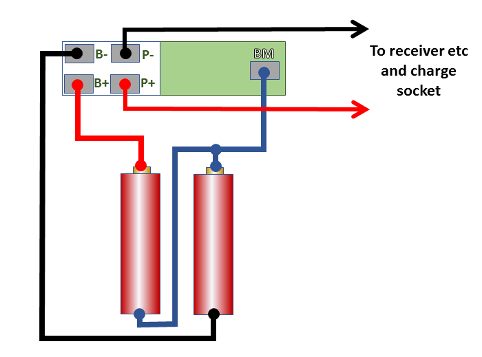
- B- = Negative terminal of Battery 1
- BM = Connection between Battery 1 and Battery 2 (ie Battery Middle)
- B+ = Positive terminal of Battery 2
Wiring for a 3S (ie three cells in series) battery pack
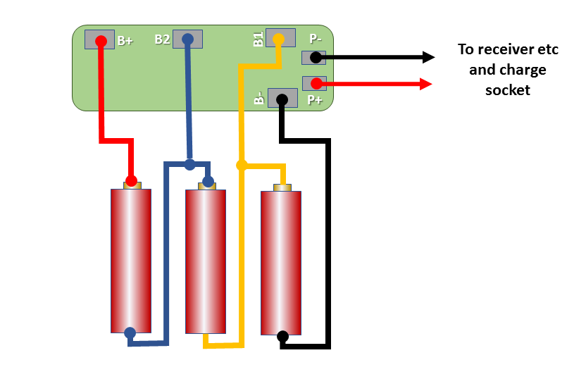
- B- = Negative terminal of Battery 1
- B1 = Connection between Battery 1 and Battery 2
- B2 = Connection between Battery 2 and Battery 3
- B+ = Positive terminal of Battery 3
There are, in addition, two solder pads (P+ and P-) which are connected to the charge socket and the rest of the circuitry for the loco (eg receiver, lighting, soundcard etc.)
Example of complete wiring for a loco with a 2S battery pack
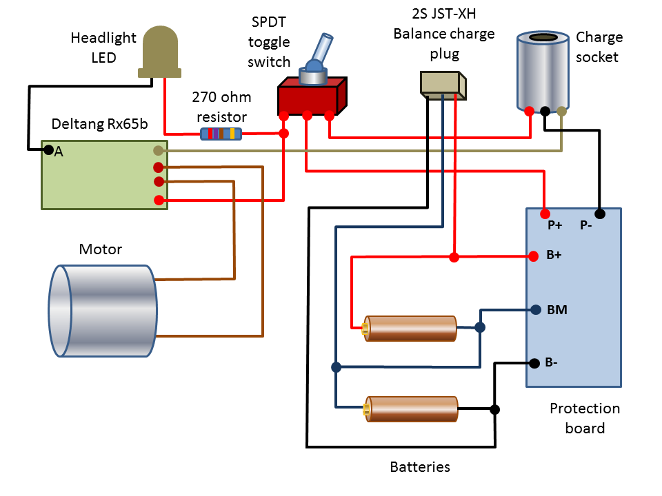
NOTE: An LED connected to Pad A will mirror the Rx LED when not being used for forward directional lighting
Example of complete wiring for a 3S 2P battery pack (ie three pairs of parallel cells in series)
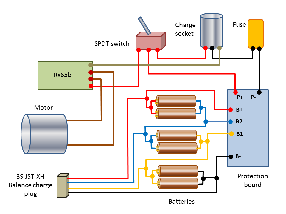
NOTE: The fuse is not really necessary as the protection board protects against short circuits
You will notice in the above diagrams that a balance charge plug has also been included in the circuit. It is advisable from time to time to balance-charge lithium-ion batteries in a pack to ensure that each cell is holding the same level of charge. If cells in the pack become unbalanced, then the pack will deteriorate and no longer hold its full charge. If the imbalance becomes acute then it could cause one or more of the cells to suffer catastrophic failure (ie your prize loco could go up in flames)
It is possible to purchase protection circuit boards which include a balance charging feature. At present RC Trains does not stock these. Please contact me if you are interested in finding out more about this type of board.
It is possible to purchase protection circuit boards which include a balance charging feature. At present RC Trains does not stock these. Please contact me if you are interested in finding out more about this type of board.