
Basic battery loco circuit
Wiring up a loco
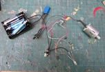
There is more than one way of wiring up a battery powered loco, but this circuit forms the basis for all twelve of my battery locos
There is more than one way of wiring up a battery powered loco, but this circuit forms the basis for all twelve of my battery locos
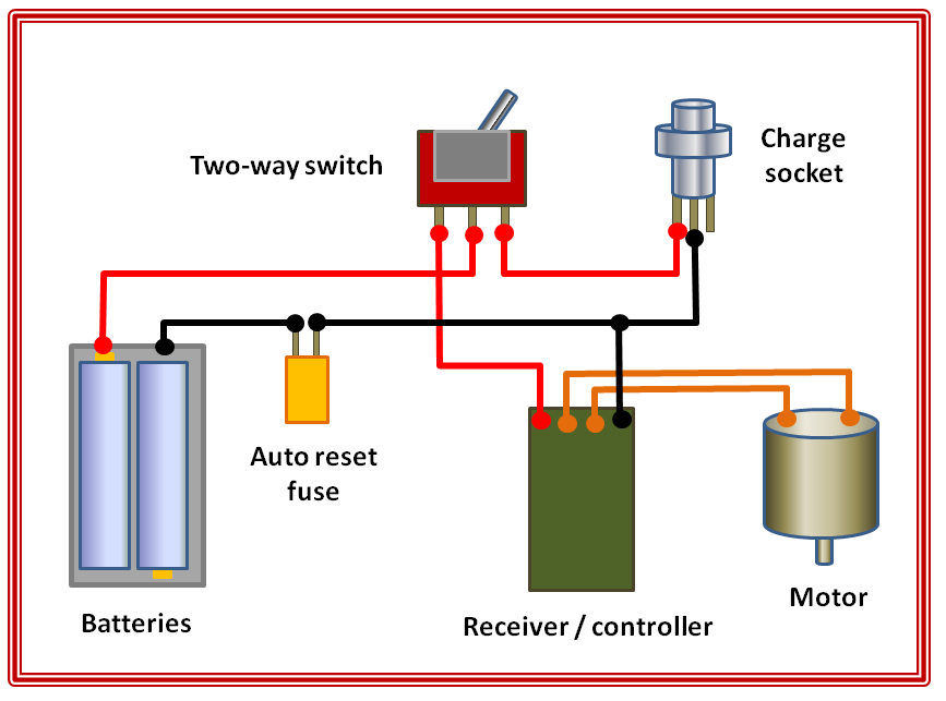
The components
Batteries
Virtually any type of battery can be used in a battery powered loco. Generally, however, rechargeable batteries are preferred. NiCd (Nickel Cadmium) batteries were once the most common batteries used in battery locos, but these have now been largely replaced by NiMh (Nickel Metal Hydride) batteries. Although Low Self Discharge (LSD) types are more expensive, they are preferrable as normal NiMh batteries discharge themselves when stored and there is nothoing more frustrating than getting a loco out and finding its batteries are flat.
I now tend to use Lithium Ion batteries as they provide more power for less space. Each cell of a li-ion battery produces 3.7v whereas each NiMh cell produces only 1.2v. Hence, ten NiMh batteries would be needed to produce 12v whereas only three Li-ion batteries are needed to provide around 12v (or 11.1v). The disadvantage of li-ion is that they are more volatile and so have to be handled carefully. They must be carefully charged and must never be over-discharged. It is advisable to use 'protected' li-ion batteries and use a battery charger which is specially designed to manage li-ion batteries. If in doubt, play safe and use NiMh LSD batteries.
Fuse
Regardless of which type of batteries you use, you should protect them from short circuits by incorporating a fuse somewhere in the circuit - preferably as near to the batteries as possible. Auto-reset fuses avoid the need for a blown fuse to be replaced but their disadvantage is they can take a long time to trip when a circuit is being overloaded - and so they are less likely to protect sensitive components in the receiver / controller. In low voltage circuits, the fuse can be placed in either the positive or the negative leads to the battery.
Two-way switch
This allows the battery to be either connected to the receiver/controller or to the charge socket. If the switch is centre-off, then it will also disconnect the battery entirely from the circuitry.
Charge socket
DC power sockets are generally used by garden railway modellers as charge sockets. These are usually mounted in a 5.5mm diameter hole and come in two sizes - 2.1mm and 2.5mm (the diameter of the plug).
The metal socket which I tend to use (and supply on the website) incorporates an internal switch contact which can be used to provide additional protection against accidental short circuits. This circuit is the one I use for my basic rechargeable wiring loom (available on the Accessories page)
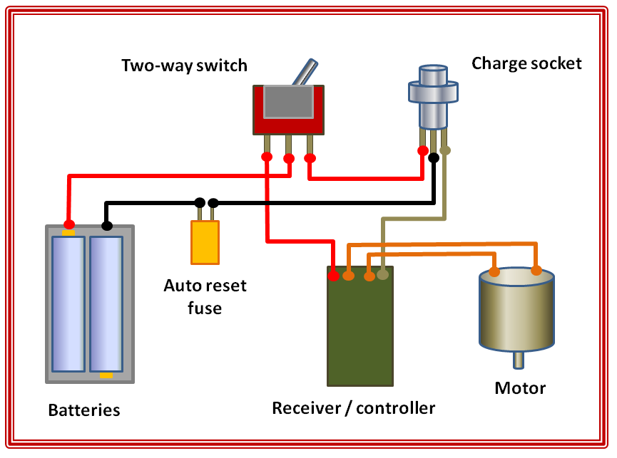
The positive lead (red) from the socket is connected through the switch and fuse to the positive terminal of the battery. The black (negative) lead is connected to the negative terminal of the battery. The grey lead is connected to the receiver/controller. When there is no plug inserted into the charge socket the receiver is connected to the negative supply. When a plug is inserted into the socket, the connection to the receiver is broken.
Receiver/controller
RCT/Deltang receiver/controllers combine a receiver with an Electronic Speed Controller (ESC) on one board. This makes them very compact and efficient. Basically, two wires are needed for the supply and two wires are connected to the motor.
Motor
The RCT-Rx65b can handle up to 3 amps which is adequate for most 16mm scale narrow gauge garden railway locomotives and smaller Gauge 1 and G Gauge locos. A daughter-board is available for the Rx65b which enables it to drive two motors (drawing up to 3A each) - or one motor drawing up to 6A.